Sigma S2Ba Betriebsanleitung
Stöbern Sie online oder laden Sie Betriebsanleitung nach Wärmepumpen Sigma S2Ba herunter. Sigma S2Ba Operating instructions Benutzerhandbuch
- Seite / 68
- Inhaltsverzeichnis
- FEHLERBEHEBUNG
- LESEZEICHEN
- Sigma / 2 Basic Type S2Ba 1
- Operating instructions 1
- Supplemental instructions 2
- Table of contents 3
- 1 Identity code 4
- Identity code 5
- 2 Safety chapter 6
- Safety chapter 10
- P_SI_0088_SW 12
- P_SI_0095_SW 13
- P_SI_0036 13
- 5 Functional description 14
- Functional description 15
- 6 Assembly 16
- Assembly 17
- 7 Installation, hydraulic 18
- Installation, hydraulic 19
- 7.1 Basic installation notes 22
- 8 Installation, electrical 23
- Installation, electrical 24
- 9 Start up 28
- Start up 29
- 10 Maintenance 31
- Maintenance 32
- 11 Repairs 34
- 11.1 Cleaning valves 35
- 11.2 Replacing the diaphragm 36
- P_SI_0029 37
- 7 6 5 4 3 38
- 12 Troubleshooting 40
- Troubleshooting 41
- 13 Decommissioning 43
- Decommissioning 44
- 14 Technical data 45
- 14.2 Shipping weight 46
- 14.3 Wetted materials 47
- Ambient conditions 47
- 14.5 Motor data 48
- 14.6 Stroke actuator 48
- 14.7 Stroke control drive 48
- Technical data 49
- S2Ba (50 Hz) S2Ba (60 Hz) 52
- 16 Dimensional drawings 53
- Dimensional drawings 54
- 1011036 Hersteller ATB 56
- ProMinent 56
- 18 Liquid ends Sigma/ 2 57
- Liquid ends Sigma/ 2 58
- 19 Wear parts for Sigma/ 2 61
- Wear parts for Sigma/ 2 62
- Risk of Explosion 64
Inhaltsverzeichnis
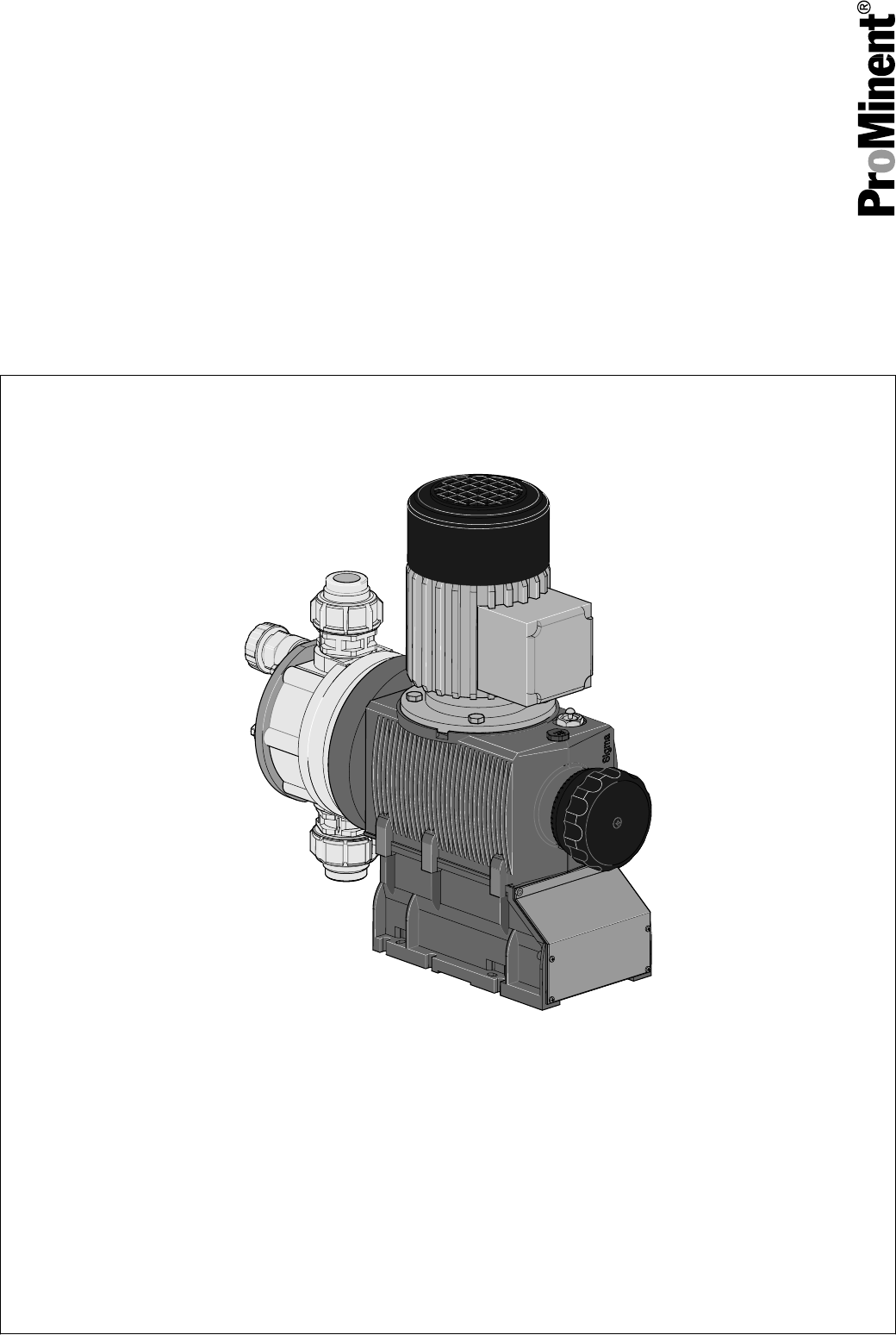
Diaphragm Motor-Driven Metering PumpSigma / 2 Basic Type S2BaOperating instructionsP_SI_0074_SWOriginal operating instructions (2006/42/EC)Part no. 98
n Drive front covern Motor fan cowlingn Terminal box cover, motorOnly remove them when the operating instructions request you to do so.In the event of
3 Storage, transport and unpackingWARNING!Only return the metering pump for repair in a cleaned stateand with a flushed liquid end - refer to the cha
4 Overview of equipment and control elements12345P_SI_0068_SWFig. 3: Overview of equipment and control elements S2Ba1 Drive motor2 Drive unit3 Stroke
20 00502575575%050251030%P_SI_0095_SWFig. 5: Adjusting the stroke lengthn 100 % = 4 rotationsn 25 % = 1 rotationn 0.5 % = 1 scale mark on stroke adjus
5 Functional description5.1 PumpThe metering pump is an oscillating diaphragm pump, the stroke length ofwhich is adjustable. An electric motor drives
1 2543P_SI_0019Fig. 8: Integral relief valve1 Spring, large2 Ball3 Rotary dial4 Spring, small5 Hose connection5.4 Multi-layer safety diaphragmWith vi
6 AssemblyCompare the dimensions on the dimension sheet and pump.WARNING!Danger of electric shockIf water or other electrically conducting liquids pe
Capacity too lowThe liquid end valves cannot close correctly if they are notupright.–Ensure that the discharge valve is upright.Capacity too lowVibrat
7 Installation, hydraulicWARNING!EX pumps in areas at risk from explosion– It is essential that metering pumps to be used in areas atrisk from explos
CAUTION!Warning of feed chemical spraying aroundPTFE seals, which have already been used / compressed,can no longer reliably seal a hydraulic connecti
Read the following supplementary information in its entirety! Should youalready know this information, you will benefit more from referring to theoper
CAUTION!Warning of backflowLiquid ends, foot valves, back pressure valves, relief valvesor spring-loaded injection valves do not constitute absolutely
CAUTION!Danger of the integral relief valve failingThe integral relief valve no longer operates reliably with feedchemicals having a viscosity of grea
7.1 Basic installation notesCAUTION!Danger resulting from rupturing hydraulic componentsHydraulic components can rupture if the maximum permis‐sible
8 Installation, electricalWARNING!EX pumps in areas at risk from explosion– Potential-free switches can be evaluated as simple elec‐trical devices (E
WARNING!Danger of electric shockA mains voltage may exist inside the motor or electrical ancil‐laries.– If the housing of the motor or electrical anci
1. Install a motor protection switch, as the motors have no fuse.2. Install an emergency cut-off switch or include the motor in the emer‐gency cut-off
CAUTION!Danger resulting from unnoticed diaphragm ruptureIf the pump has been ordered with an electric diaphragm rup‐ture sensor, it must also be elec
* at rated loadThe contacts are potential-free.The pacing relay is a N/O as standard.Supply voltage for pacing relay PCBAvailable supply vol‐tagesMain
9 Start upWARNING!EX pumps in areas at risk from explosion– An appropriately skilled operative should check whetherthe appropriate installation infor
CAUTION!Possible environmental and material damageIn event the red gear bleeding plug is sealed, during opera‐tion it prevents any pressure compensati
Table of contents1Identity code... 42 Safety chapter...
When operating the integral relief valve close to the openingpressure, a minimal overflow into the overflow line can occur.Only adjust the stroke leng
10 MaintenanceWARNING!EX pumps in areas at risk from explosion– Ensure correct operation in general, particularly of thepower end and bearing, by reg
WARNING!Warning of dangerous or unknown feed chemicalShould a dangerous or unknown feed chemical be used: Itmay escape from the hydraulic components w
When using abrasive feed chemicals, the diaphragm service life isreduced. In such cases, more frequent checking of the diaphragm is rec‐ommended.Data
11 RepairsWARNING!EX pumps in areas at risk from explosion– Generally check the proper operation of the system, par‐ticularly of the power end and be
11.1 Cleaning valvesUnsuitable spare parts for the valves may lead to problemsfor the pumps.–Only use new components that are especially adapted tofi
11.2 Replacing the diaphragmThird party spare parts for the pumps may lead to problemswhen pumping.–Use only original spare parts.–Use the correct sp
P_SI_002923A1Fig. 22: Tolerance range of the flap on the backplate1 Diaphragm2 Backplate3 FlapA Tolerance range12. Should this not work, remove dirt o
1. If the inside of the diaphragm rupture sensor has become damp ordirt has penetrated it: replace.7 6 5 4 321P_SI_0020_SWFig. 23: Section through the
6. After a successful test, screw the transparent cover onto the dia‐phragm rupture sensor and then continue at the top by fitting thediaphragm.Electr
1 Identity codeS2Ba Sigma 2 Basic Type H Main power end, diaphragm Type: Capacity_ _ _ __ _ Performance data at maximum back pressure and type: se
12 TroubleshootingWARNING!EX pumps in areas at risk from explosion– Ensure correct operation in general (no leaks, unusualnoises, high temperatures,
CAUTION!Warning of feed chemical spraying aroundFeed chemical can spray out of the hydraulic components ifthey are manipulated or opened due to pressu
**WARNING!Warning of escaping feed chemicalWhen dosing combustible feed chemicals or in hazardouslocations, under no circumstances must the second dia
13 DecommissioningWARNING!Fire hazard with flammable mediaOnly with combustible media: These may start to burn whencombined with oxygen.– During fill
WARNING!Warning of eye injuriesWhen opening the relief valve, a spring under high tensioncan jump out.– Wear protective glasses.CAUTION!Danger of dama
14 Technical dataWARNING!Risk of personal injuriesPlease observe the ”Supplement for modified version“ at theend of the chapter!It replaces and suppl
Type Minimum pump capacity at maximum back pres‐sureMaximumstrokerateSuction lift Permissibleprimingpressure,suction sideConnectorsize bar psi l/h gp
Types Material version Shipping weight kg07120 ... 04350 PVT 16 SST 2414.3 Wetted materialsMaterial ver‐sionLiquid end Suction/pres‐sure connecto
14.4.3 Air humidityData Value UnitMaximum air humidity *: 92 % rel.humidity* non-condensing14.5 Motor dataFor motor data - refer to the nameplate.Mo
Contact loading, max.at voltage Maximum current30 V DC 1 A.The diaphragm rupture sensor is an NC.–For safety reasons we recommend connecting to a pro‐
S2Ba Sigma 2 Basic Type_ Connection data - refer to nameplate on motor1 No motor, with B14 flange, size 71 (DIN)2 No motor, with C 42 flange (NEMA)3 N
5–25 V DC, in accordance with Namur or DIN 60947-5-6, potential-freedesign.Data Value UnitNominal voltage * 8 VDCPower consumption - active surfaceunc
During operation with an automatic stroke length adjustment controltogether with a variable speed motor, the stroke rate must not fall below30 strokes
15 Diagrams for setting the metering capacity050100150200250300350400450806040200 100 120043500722007120161301609016050p [bar]S [%]C [l/h]C [l/h]ABp
16 Dimensional drawings–Compare the dimensions on the dimension sheet andpump.–All dimensions are in mm.Dimensional drawings 53
Dimensional drawings 54
Dimensional drawings 55
17 Motor data sheet standard motortension nominale380 480/220 280Vcourant de démarragefoisMotor Datenblatt / Motor data sheet / Fiche technique pour
18 Liquid ends Sigma/ 2P_SI_00241545623Fig. 26: Liquid end Sigma/ 2 130-DN 15 and 350-DN 25 PVTItem. Description Type 16050,16090, 16130Type 04350,07
P_SI_0086_SW******10Fig. 27: Sigma/ 2 PVA relief valve-AItem. Description Type 16050,16090, 16130Type 07120,07220Type 04350,10 Relief valve, compl. 1
P_SI_0025_SW1545623Fig. 28: Liquid end Sigma/ 2 130 and 350 SSTItem. Description Type 16050,16090, 16130Type 04350,07120, 072201 Spring * *2 Ball * *3
2 Safety chapterCAUTION!These operating instructions include notes and quotes fromGerman guidelines relating to the system operator's scope ofre
***P_SI_008710Fig. 29: Sigma/ 2 SSA relief valve-AItem. Description Type 16050,16090, 16130Type 07120,07220Type 04350,10 Relief valve, compl. 16 bar S
19 Wear parts for Sigma/ 219.1 StandardSpare parts kit Types 16050, 16090, 16130 Types 04350, 07120, 07220FM 130 - DN15 1035951 FM 350 - DN25 1035
Spare parts kits PVT (liquid ends)Liquid end Types 16050, 16090, 16130 Types 07120, 07220, 04350FM 130 - DN 15 1046472 -FM 350 - DN 25 - 1046475Spare
20 EC Declaration of Conformity for MachineryIn accordance with DIRECTIVE 2006/42/EC OF THE EUROPEAN PAR‐LIAMENT AND OF THE COUNCIL, Appendix I, BASI
21 EC Declaration of Conformity for Machinery Used in Areas atRisk of ExplosionWe,n ProMinent Dosiertechnik GmbHn Im Schuhmachergewann 5 - 11n DE - 69
66
986271, 2, en_GB© 2011ProMinent Dosiertechnik GmbHIm Schuhmachergewann 5-1169123 HeidelbergGermanyTelephone: +49 6221 842-0Fax: +49 6221 842-612ema
n Observe the general limitations with regard to viscosity limits, chem‐ical resistance and density - see also ProMinent Resistance List (inthe Produc
An instructed person is deemed to be a person who has been instructedand, if required, trained in the tasks assigned to him/her and possible dan‐gers
CAUTION!Warning of feed chemical spraying aroundFeed chemical can spray out of the hydraulic components ifthey are manipulated or opened due to pressu
Weitere Dokumente für Wärmepumpen Sigma S2Ba


Verwandte Produkte und Handbücher für Wärmepumpen Sigma S2Ba
 (77 Seiten)
(52 Seiten)
(32 Seiten)
(4 Seiten)
(77 Seiten)
(52 Seiten)
(32 Seiten)
(4 Seiten)
© 2020, manymanuals.de. Alle Rechte vorbehalten. | 1.419 s |
 Manymanuals.com
 Manymanuals.de
 Manymanuals.fr
 Manymanuals.it
 Manymanuals.pl
 Manymanuals.cz
 Manymanuals.es
 Manymanuals-pt.com
Kommentare zu diesen Handbüchern